Basic IED Electronics

$23,500.00

 
Upon completion of this course, participants will have the knowledge, skills and abilities to:
 

  • Improve the safety, efficiency, and effectiveness of a bomb squad responding to an IED incident
  •  

  • Improve threat assessment and forensic abilities of a bomb squad by enhancing their knowledge of IED construction techniques.
  •  

  • Enhance in-house training by enabling the bomb squad to recognize device designs from different sources and exploit those designs to produce more realistic training aids
SKU: IE-TC-0008 Categories: ,

Description

 
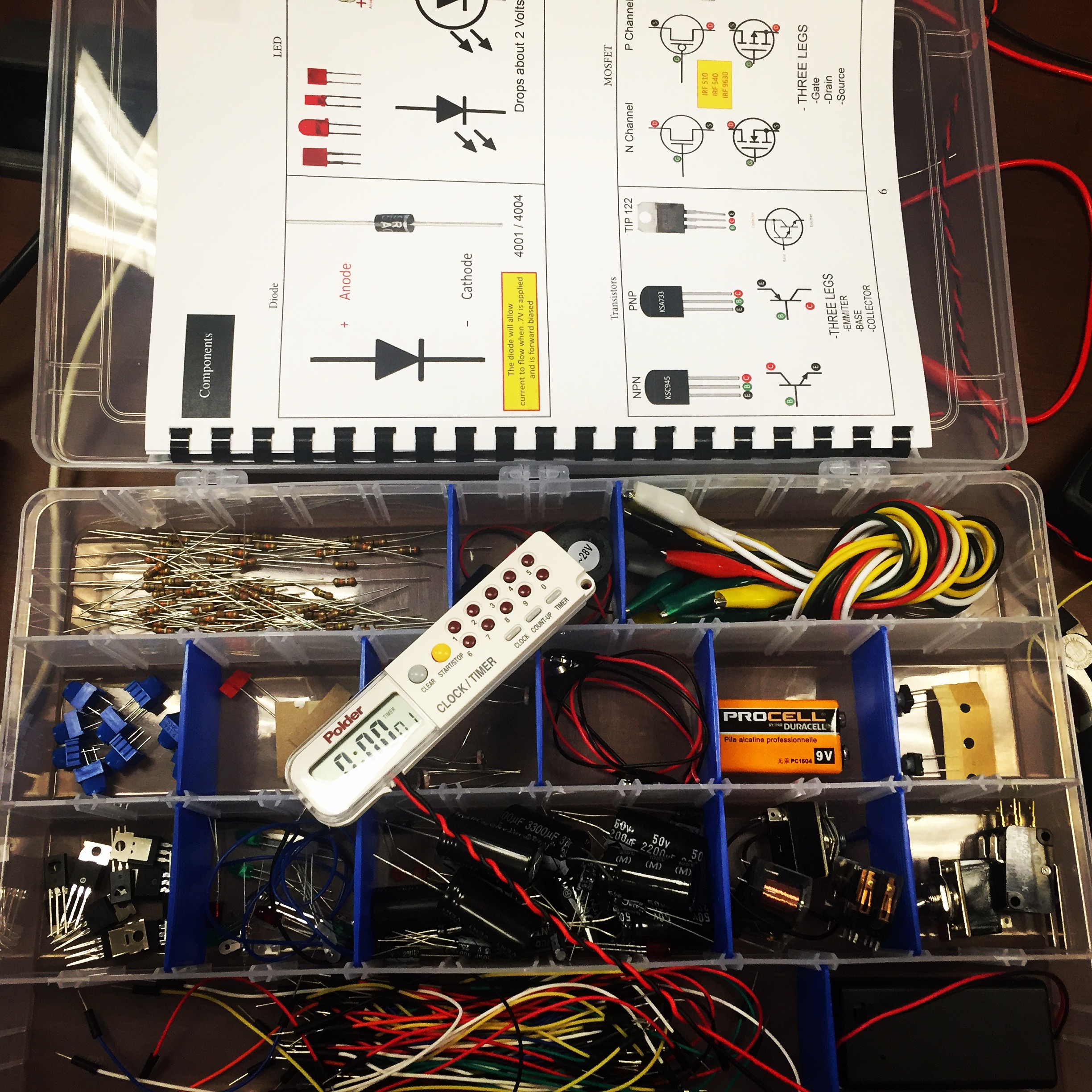
This 40hr EOD Electronics Course reveals how modern electronics offer the terrorist a broad range of options for device design and construction. Assuming no previous knowledge of electronics, participants gain a practical understanding of devices such as collapsing circuits (traditional and solid state), modification of commercial technologies for use in IEDs, and remote-controlled IEDs (RCIEDs), including dual tone multi-frequency (DTMF), and other coding systems. The course begins with an outline of electrical theory and Ohm’s Law, followed by an introduction to a wide variety of electronic components. Components will be introduced as schematics, physical components, radiographs or as post blast photographs as needed to reinforce training topics associated with EOD Tasks.  Emphasis is placed on the characteristics of electronic components and circuits that make them attractive to the terrorist and the characteristics that often cause training devices to fail. Students learn primarily by building circuits and soldering those circuits together on provided printed circuit boards.


Training Objectives:


Understand the fundamentals of Electronic Theory

  • The anatomy of an atom
  •  

  • Conductors and insulators
  •  

  • The relationship between voltage, current and resistance in DC Circuits
  •  

  • Series and parallel circuits
  •  

  • Ohm’s law
  • Identify the function of an electronic switch in a circuit
  •  

  • Describe how a switch works
  •  

  • Identify the schematic symbols for switches
  •  

  • Use a soldering iron to prepare a switch for use in a breadboard
  •  

  • Demonstrate how to place components in a breadboard
  •  

  • Relate an electronic schematic to components on a breadboard
  • Identify the schematic symbols for a different types of resistors
  •  

  • Determine a fixed resistor’s value (color code)
  •  

  • Identify variable resistors
  •  

  • Use resistors in a circuit
  •  

  • Describe how relays are used in an electrical circuit
  •  

  • Recognize the schematic symbol for a relay
  •  

  • Discuss how relays are configured in a circuit
  •  

  • Describe how capacitors are used in an electrical circuit
  •  

  • Recognize the schematic symbols for capacitors
  •  

  • Discuss how capacitors are configured in a circuit
  •  

  • Summarize how semiconductors are used in the electrical circuit
  •  

  • Describe semiconductor theory
  •  

  • Describe the relationship between N and P-type materials
  •  

  • Recognize the schematic symbol for a diode
  • Explain how transistors are used in an electrical circuit
  •  

  • Identify the schematic symbol, the legs, and the function of a transistor
  •  

  • Determine how transistors are configured in a circuit
  •  

  • Discuss how MOSFETs are used in an electrical circuit
  •  

  • Identify the schematic symbol, the legs, and the function of a MOSFET
  •  

  • Determine how MOSFETs are configured in a circuit
  •  

  • Discuss how SCRs are used in an electrical circui
  •  

  • Identify the schematic symbol, the legs, and the function of a SCR
  •  

  • Determine how SCRs are configured in circuits
  •  

  • Generalize how integrated circuits are used in the electrical circuit
  •  

  • Recognize an IC in a radiograph
  •  

  • Identify the pin configuration of an IC chip
  •  

  • State the purposes of a 555 timer
  •  

  • Describe how logic ICs can be used in an electrical circuit
  •  

  • Identify the pin configuration of a logic chip
  •  

  • Explain the use of a truth table
  •  

  • Identify schematic symbols for logic gates
  •  

  • Basic Programming Concepts
  • Functions, arrays and Loops
  •  

  • Microcontroller Input/ Output
  •  

  • Integrating sensors (PIR, LDR, Ultrasonic)
  •  

  • Radio Communications using Arduino (HOPE RF RFM69 and RFM95)


Schedule of Events: 

Day 1- DC Theory Lecture and Lab (Resistors Batteries, Capacitors and switches)


Lab: Breadboard simple circuits and test with supplied multimeter

Solder breadboard leads to switches
 

Day 2- Relays, Diodes, Transistors, MOSFETs, and SCRs Lecture and Lab


Labs: Breadboard 5 historical IEDs using supplied components from lecture
 

Day 3-Logic Chips and RCIED Circuits


Labs: Build RFT-2 on supplied PCB

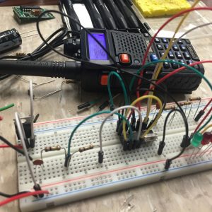
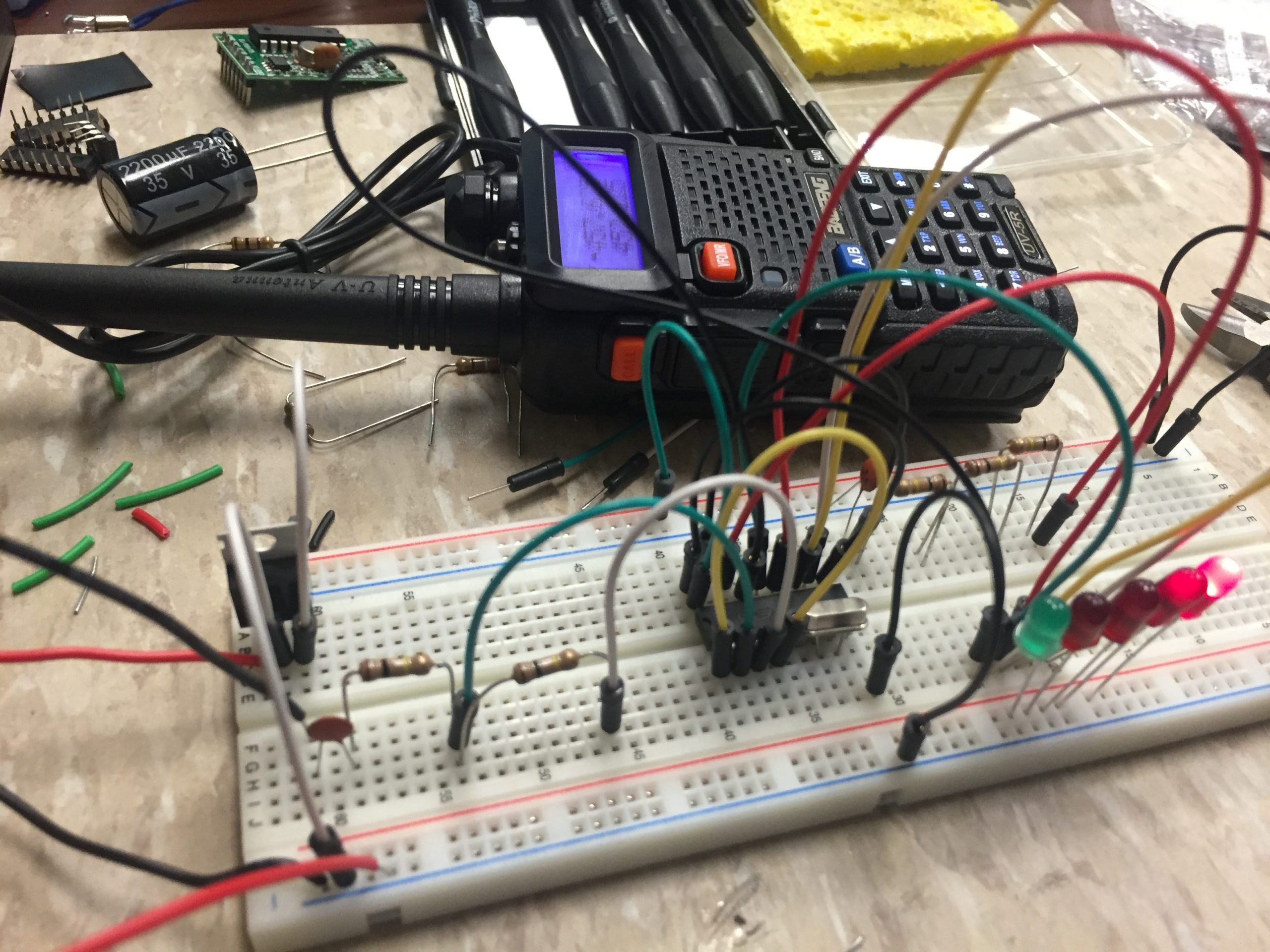
Build DTMF PIC IED Circuit Board and interface with COTS radio (Similar to DTMF-11)


Day 4- Programming Concepts and Arduino Applied to IEDs


Labs: Arduino Light Meter (from source code)
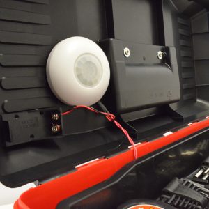
Arduino PIR Counter


Day 5- Capstone IED Team Build


Students will split into teams of 4 and build a modern microcontroller based RCIEDs with sensors. Source code will be provided.


Deliverables:

  1. Lab kit (Breadboard, Multimeter, Soldering Iron, Parts Kit, COTs timer and DTMF Radio, and Arduino boards)

  2. Student Training guide with schematics & diagrams

  3. CAD files and source code (from the labs)

  4. Certificate of Completion